Technical Info
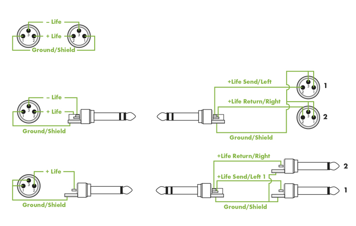
Wiring diagrams and assembly instructions
Click here for an overview of our standard assignment / wiring diagrams and assembly instructions as well as our splice length information. In the case of deviating desired configurations, please send us your connection diagram as a sketch, assignment table or brief description. We are looking forward to your contact.

Audio Technology in General: Hum and Interference
First and foremost musicians want to play music. Plug in, turn on, and then – you hear hum like a buzz saw. It is not very easy to explain how this hum, mostly caused by so-called ground loops, is created. For musicians and roadies it is important to get some idea what causes this annoying by-product in audio systems and what can be done about it.
Wherever we go in our civilized world, dangerous forces lurk in the shadows, ready to disturb the peace of our pure, innocent sound signals. Running motors, transformers, mobile phones, electric tooth brushes – in short, a whole army of possible sources of interference. Every cable is being threatened by all kinds of external interference. Some of these hidden forces travel through air in form of radio waves, while others sneak through the normal electrical system in our house, for example when we switch on fluorescent lights, dimmers or the power supply of an amplifier.
With PA systems sometimes you have no other choice but to use long cable runs between stage and mixer. Interference caused by fluorescent lights, for example, can be picked up by these cables and cause “humming“, “buzzing“ or “crackling“.
Typical causes for these problems are the power supplies that are required for most audio equipment.
All electronics, from effect units to instrument amplifiers, require a power source of 115 or 230 V. If you have ever taken a look at a power cable you have noticed that it has three wires, usually black, white, and green: Phase = carries the voltage, zero = grounding at the generating plant, and the protective earth (PE) or equipment grounding conductor = grounding at the house to the foundation earth or ground.
On most units the conductive parts, surfaces and ground connection for the cable are internally connected directly to the PE contact, and thus to the protective earth conductor at the power outlet. The purpose of the protective conductor is to protect. It discharges the voltage if there is a defect in the unit or the phase touches the housing. This should normally trip a safety breaker.
Even though all we want to do is make music, (un)fortunately the subject of required power supply safety standards result from a number of legal guidelines that were not randomly created by some officials just to make our lives more difficult. The opposite is the case, because it could be a matter of life or death!
The voltage of 115 V with 60 Hz in the US, and even more so the 230 V with 50 Hz commonly used in Germany/Europe will endanger your life if you come in contact with it. This makes the operation of amplifier and PA equipment, and even more so lighting systems that are powered by a so-called three-phase current, dangerous. Here we are dealing with currents of up to 380 V !!! They are guaranteed to be lethal, a fact that is supported by accident statistics.
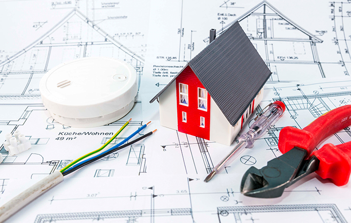
Everyone who makes music would like to show off his or her talents at public events. To do this, in most cases you need technical equipment. And here the challenges begin. Even a performance at the town hall in front of only 100 – 150 people is a public event.
Such events are governed by conditions and regulations which have only one purpose: to protect the public and performers from injury or worse. The organizer of the event is mostly responsible for ensuring that escape routes and emergency exits are available, the stage is built safely and that appropriate power sources and wiring are used. And now we have come full circle – back to supplying the electrical power.

Protection classes IP code
(DIN 40050 Teil 9, DIN EN 60529)
Z1 - Protection against foreign objects
0 - No protection
1 - Protection against solid foreign objects Ø > 50.0 mm [1.97“]
2 - Protection against solid foreign objects Ø > 12.5 mm [0.49“]
3 - Protection against solid foreign objects Ø > 2.5 mm [0.1“]
4 - Protection against solid foreign objects Ø > 1.0 mm [0.04“]
5 - Dust protection
6 - Dustproof
Z2 -Protection against water
0 - No protection
1 - Protection against dripping water
2 - Protection against dripping water with enclosure inclination ≤ 15°
3 - Protection against splashing water up to ≤ 60° from the vertical
4 - All round protection against splashing water
5 - All round protection against water jets
6 - All round protection against hose water
7 - Watertight when submerged (1 m / 3.28 ft.) for 30 min
8 - Watertight when permenantly submerged (1 m / 3.28 ft.)
Audio Technology in General: The Proper Cable!
Let‘s first start with the instrument, the guitar, the bass, and the keyboard.
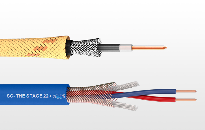
On stage, the kind of cables that are usually used to connect instruments and amplifiers are single-wire audio cables with shielding. Interference from external sources can cause trouble even if short cables are used. The cable shielding consists of a wire mesh or foil that completely surrounds the actual conductor. The shielding protects the sound-carrying wire against interference caused by electrical and electro-magnetic waves. But the problem for a single-wire shielded cable is that we only have one dedicated positive signal “hot“ wire (+), while the negative “cold“ phase (–) is shared with the outer shielding. This works fine as long as outside interference is low. The shield functions simultaneously as the second conductor that is required to complete the circuit.
For the transmission of audio signals through single-wire shielded cables, interference-free transmission is limited to cables that are only a few meters long.
Unbalanced cable connections
Unbalanced cables (such as your typical guitar cord) are single-wire audio cables with an inside conductor and outside wire braiding. The plug only requires two contacts (positive “hot“ phase and shielding).
The phase (“hot“) transmits the audio signal from the source to the destination. The shielding serves as protection and as the negative or “cold“ phase.
Balanced outputs
DI boxes
Stage microphones
Mixing board L/R master outputs
Mixing board sub groups
Mixing board matrixes
Mixing board monitor paths
Aux paths
Balanced cable connections
Mixing board XLR inputs
Mixing board balanced line-inputs
Mixing boards return
Effect units
Balanced cables even very long ones are immune to electro-magnetic interference and ground loops.
Balanced cables consist of shielding (1) and two conductors (Fig. 3). The audio signal is transmitted independently from the shield and ground. Interferences that are intercepted by the shield and ground wire do not affect the audio signal, thus the term ungrounded. The two conductors are wired phase inverted.
This means that the phase in one conductor is inverted by 180 degrees. Due tothis opposite phasing, the electro-magnetic interference signals that affect the cable from the outside reach both conductors simultaneously and cancel each other out.
For ungrounded balanced transmission to work, it is necessary that the inputs and outputs on the connected devices are both balanced. This can be accomplished electronically, i.e. through the use of balanced input amplifiers with common mode rejection or output amplifiers with optimized unbalanced output voltage ( a-conductor to b-conductor).
Today we can assume that electronically balanced inputs and outputs are superior to most transformer-balanced ones regarding transmission parameters such as frequency response, distortion factor, common mode suppression, and resistance to over-modulation. Nevertheless it is often necessary to use balanced cables without ground.
Genuine ungrounded balanced audio transmission is only possible through the use of audio transformers. These transformers are optimized to handle lowfrequency audio signals. But despite the fact that a vast selection is available on the market many of them can only be used for the ungrounded transmission method. Those who want genuine transmission quality with the best possible common mode rejection have to depend on toroidal core transformers.
Microphone cables connected to mixing boards carry very low voltage levels (milli-volt range) and are therefore extremely sensitive to interference. This is why it is very important that they always be ungrounded-balanced. But with return cables leading from the mixing board to the amplifier, the risk of interference is not quite as high, because the strength of the signal can reach several volts. Therefore, using ungrounded balanced cable to route the signal to the amp is not absolutely required.
However, the only way to completely eliminate all possibility of interference is by insisting that all cables incorporate an ungrounded balanced design.

Audio Technology in General: The cable shields
commonly grounded or separately implemented?
For the sheer reason of crosstalk attenuation improvement, we give preference to separate grounding. In a metaphorical sense, the multicore is an extension link for balanced audio lines connecting the audio sources up on stage to the inputs of the mixing desk in the hall. Therefore, it seems quite logical and sensible if we stick to separate shielding on the extended path from the socket connector on stage (via the multicore) to the socket connector on the mixing desk.
Another argument emerges from the ground "potential:" i.e., the point within the system where the screening/s is/are connected to ground, and thus connecting with the PE potential of the location’s lowvoltage power grid. Basically, this should be the input of the mixing console. This is the central point where all the screens of the multicore system are linked to each other. Here we find all screen connections centrally joined, irrespective of the moment, whether on the XLR or the phone plug on the 0 V = ground potential of the internal power supply and thus on PE potential.
With consistently balanced cabling that uses separate shielding for each single line, the XLR input socket on the stagebox is precisely equivalent to the console input to which it is linked. If you connect a condenser microphone here and activate phantom power on this channel, the operating current of the microphone will only flow through this channel. The separate shielding has even greater benefits when connecting mains-powered audio sources. In most cases we may well assume that down in the hall, where the mixing console has been placed, the PE potential at the power socket will not be exactly identical to the PE potential at the power socket up on stage. If a mains-powered device is connected with its output to the stagebox, compensating currents may be introduced via the shielding of the audio line, resulting in a classical ground loop. With separate shielding in most cases only this single channel will be affected. Trouble-shooting is relatively easy; inserting a DI box in that line with GND lift (XLR pin 1 isolated) will eliminate the problem. However, if all screens are joined at the stagebox or in the connector and several mains-powered sources are connected, the humming noise can multiply. Not only will potential compensating currents drain off via the console; they will also flow between the connected devices via the common shielding.
One remedy that has spread around among “stage practicioners”, but is hazardous, is when the ground wire is taped or disconnected on devices or power cables. This may lead to temporary sonic success, but is nevertheless EXTREMELY DANGEROUS.
A popular misconception to help save costs is by joining the screens because only the a-wire and the b-wire of a line must be crimped and more audio lines can be used on each connector. However, it is neither the connector, nor the cable, nor the crimping contacts that produce costs there – it is ultimately the technican, who has to braid, solder and connect everything to the screens. Often the screens are then linked to the PE terminal of the connector. Here, again, the safety aspect is neglected. The terminal on the connector has been marked as CHASSIS = PE terminal by the manufacturer. The connector housing is conductive and must lie on PE potential according to VDE 0100. Doing it any other way is unfortunately forbidden, and we should stick to this protocol. Screens just do not belong at this terminal. The construction of stagebox and multicore systems is not just a matter of pure signal transmission. After all, you don't want the technology of setting up at a gig have to be so frustratingly complex that it takes all the joy out of public performance for the many amateur musicians and weekend warriors who are simply trying to show off their talents and be more social. Here it’s about tough real-world gigs that just won’t allow you to go trouble-shooting for hours. This could easily be avoided with careful planning and spending a little more money.
In a recent interview with Beat magazine, Pascal Miguet, Product and Sales Manager / Authorised Representative at Sommer cable, provides expert insights into the intricacies of cable shielding and different types of shielding.
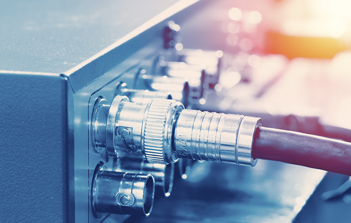
Transmission lengths of video cable
Download Overview of transmission lengths
The values given are guideline values and in most cases - due to the high production quality of the respective SOMMER CABLEs - far better results can be achieved. We will be happy to provide samples for tests. Please send us an inquiry to info@sommercable.com

FRNC Explanation
Explanation of testing procedures according to VDE 0472, Part 804
FRNC Test Type A
A cable sample measuring 60 cm (2 ft.) in length is vertically suspended in the center of a metal box 1200 mm tall by 300 mm wide by 400 mm deep (circa 47 x 12 x 16“). A gas burner with a defined flame is installed in such a way that its axis is tilted by 45° in reference to the vertical. The flame hits the cable sample about 100 mm/4“ above the lower end. The flame burns until the conductor or the topmost metal shielding shows through, but no longer than 20 seconds. To pass the test, either the test sample must not catch fire, or if it does start to burn it must then extinguish itself, and whatever damage is caused by the flame‘s heat must fail to reach the top end of the tested cable sample.
FRNC Test Type B
A cable sample measuring 60 cm (about 2 ft. in length) is vertically suspended in the center of a metal box (1200 mm tall by 300 mm wide by 400 mm deep (circa 47 x 12 x 16“). A gas burner with a defined flame is installed in a way that its axis is tilted by 45° in reference to the vertical. The flame hits the cable sample about 100 mm/4“ above the lower end for about 1 – 2 minutes, depending on the weight of the sample. The test is successful if the test sample did not burn or if the flame that resulted extinguished itself and the damage caused by the heat of the flame did not reach the top end of the tested cable sample.
FRNC test type C
Cable samples, each measuring 360 cm/14“ in length, are fastened side by side to a ladder-like test rack. This test rack is inserted vertically into a kiln, at a distance of 150 mm/6“ to the back of the kiln. The flame is directed right against the flame samples at a height of approximately 60 cm/2 ft., at a temperature of approximately 800°C/1472°F, by a burner about 250 mm/10“ wide. The exposure time is 20 minutes. The test is successful if the ensuing flame extinguishes itself and the damage caused by the heat of the flame did not reach the top end of the tested cable sample.
Information on EU Construction Products Regulation 305/2011:
The EU Construction Products Regulation is the latest directive which since 2017 has harmonized the reaction to fire of construction products that are permanently installed in buildings and have an impact on the building's performance. There are seven Euroclasses, Aca to Fca , to subdivide the flame spread and heat development, whereby cables with functional endurance are not subject to the CPR requirements.
The former regulations of the FRNC classes and test procedures are therefore outdated, which does not mean that the FRNC specifications like self-extinguishing/flame retardant properties specified by us so far have thus changed. Unless otherwise specified in our offers and shipping documents, our cables are classified into the Euroclass Fca. Higher ratings of some cables like e. g. certain data or control cables, which are mainly used in building installation, are rated with their respective classes.
Unfortunately every higher classification entails substantial test and certification fees per cable, which is why we, on our part, do not automatically classify each installation line anew to keep your prices stable. Upon request, we will gladly put you in touch with qualified laboratories.
Further helpful information for planners and installers about the EU Construction Products Regulation can be found here:https://www.zvei.org/en/association/divisions/german-cable-makers-association-division/low-fire-hazard-cables-improve-safety/

AV Terminology